This document outlines the various truth collectors available in the DIRSIG4 model.
The truth collectors are objects that extract information about important image formation parameters on a per-pixel basis. For example, the user can extract the ground sampling distance (GSD) for each pixel, which will vary across the focal plane due to distances from the sensor to the ground resulting from ground height variation or off-axis viewing. Because a pixel may contain multiple contributions, some of the truth collectors provide statistical summaries. For example, the temperature truth reports the average temperature and the variance in temperature within a pixel because multiple objects (with unique temperatures) might be present within a pixel.
Each focal plane in a DIRSIG instrument can have its own set of truth collectors configured. Truth collectors are run for each capture (or "read out") of the corresponding focal plane. In some cases, the truth collectors gather radiometric properties which are valid across the spectral bandpass of the corresponding focal plane.
Truth Image File
The parameters gather by the various truth collectors are stored into a 3-D image cube, where each "band" in the image contains information about a specific image formation parameter.
|
|
For specifics on the format of these binary image files, consult the Output Image Format document. |
The truth collectors can be configured in the user interface, or manually
within the .platform file. Similar to the options for output image files
produced by the focal plane capture methods, the user can specify the output
file "schedule", which allows for:
-
A single image file for the whole simulation,
-
A separate image file for each task, or
-
A seperate image file for each capture
The XML schema for the truth collection in the .platform file is as
follows:
          <focalplane>
            ...
            <truthcollection>
              <enabled>true</enabled>
              <imagefile>
                <basename>example_truth</basename>
                <extension>img</extension>
                <schedule>simulation</schedule>
              </imagefile>
              <collectorlist>
                ...
              </collectorlist>
            <truthcollection>
          </focalplane>
where each focal plane can have one or more <truthcollection>
elements configured. The <collectorlist> element contains one or
more <collector> elements that configure individual truth collectors.
Although the graphical user interface is the easiest way to configure
the various truth collectors, the description of each collector
in the following sections will also include the XML schema for the
collector for users that wish to directly manipulate the .platform
file.
|
|
Although this option is currently not available via the graphical
user interface, the user can configure more than one <truthcollection>
in the .platform file. The reason for doing this is that the user
can route truth for different collectors to different truth image files.
For example, collection #1 might output material truth to the image file
truth_materials.img and collection #2 might output shadow truth to
the image file truth_shadows.img.
|
Truth Collectors
Material
The "material" truth collector set extracts information about what materials are present within each pixel. Since a pixel may contain more than one material, this collector reports the materials in various ways:
-
The collector gathers information on the first material(s) encountered regardless of if it is opaque (non-transmissive) or partially transmissive.
-
The "Top ID" tells you the ID of the material that was the largest contributor (spatially weighted fraction) within the pixel.
-
The "Top Fraction" tells you what spatially weighted fraction of the pixel the "Top ID" material was within the pixel.
-
The "Unique IDs" tells you how many unique materials are contained within the pixel.
-
-
The collector gathers information on the first opaque (non-transmissive) material(s) encountered within the pixel:
-
The "Top ID", "Top Fraction" and "Unique IDs" are reported for only opaque materials.
-
-
The collector gathers information on the first partially transmissive material(s) encountered within the pixel:
-
The "Top ID", "Top Fraction" and "Unique IDs" are reported for only transmissive materials.
-

|
|
To obtain precise pixel fractions for specific materials, consider using the Material Abundance truth collector. |
This truth collector set is configured in the .platform file via the following
<collector> syntax:
                <collector>
                  <name>Material</name>
                </collector>
Instance Index
Internally, each instance of every object has a unique "index" that can be used to resolve where instances of each object are located at a given time. The "instance index" truth collector gathers the unique instance index that dominates the spatial area of the pixel.
Geometry Index
Internally, each base geometry object has a unique "index" that can be used to resolve geometry shared by instances and the source of that geometry. The "geometry index" truth collector gathers the unique base geometry index that dominates the spatial area of the pixel.
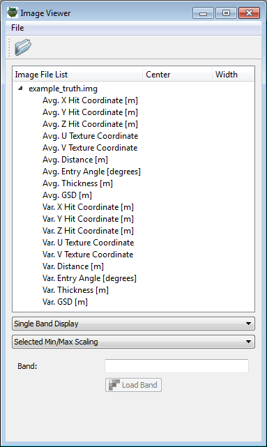
Intersection
The "intersection" truth collector gathers information about objects intersected within a pixel. Since a pixel may contain more than one material, this collector reports both the average and variance in these parameters.
The average and variance of the following parameters are collected:
-
The XYZ location of the intersection in the Scene ENU coordinate system.
-
The UV mapping coordinate (these coordinates will be
-1if there is no UV coordinate information associated with the object). -
The distance (in meters) from the camera focal point to the object.
-
The relative angle (in degrees) between the pixel ray and the object normal.
-
The thickness (in meters) associated with the object.
-
The ground sampling distance (GSD) of the pixel (in meters).
|
|
To get geographic intersection information (rather than values in the Scene ENU coordinate system) use the GeoLocation collector. |
|
|
A useful way to determine the Scene ENU coordinates of an object in a scene is to render the scene with the Intersection truth enabled and then load the X, Y and Z intersection bands as the Red, Green and Blue bands in the image viewer. As you hover your mouse over any pixel, the "data value" will be the XYZ location of that object. |
This truth collector is configured in the .platform file via the following
<collector> syntax:
<collector>
<name>Intersection</name>
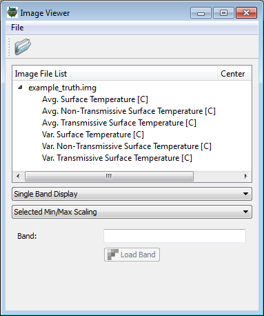
</collector>Temperature
The "temperature" truth collector gathers temperature information about objects intersected within a pixel. Since a pixel may contain more than one material, this collector reports both the average and variance in the temperature.
The average temperature and variance in temperature are collected for the following:
-
The collector gathers information on the first surface(s) encountered.
-
The collector gathers information on the first opaque (non-transmissive) surface(s) encountered within the pixel.
-
The collector gathers information on the first partially transmissive surface(s) encountered within the pixel.
This truth collector is configured in the .platform file via the following
<collector> syntax:
<collector>
<name>Temperature</name>
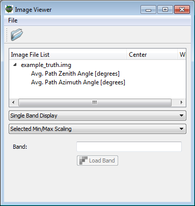
</collector>Path Angle
The "path angle" truth collector gathers information about the average angles for the pixel.
-
The average zenith (declination) angle (in degrees).
-
The average azimuth angle (in degrees).
This truth collector is configured in the .platform file via the following
<collector> syntax:
<collector>
<name>PathAngles</name>
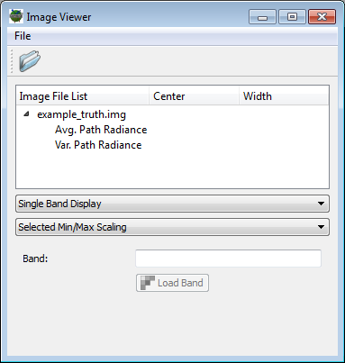
</collector>Path Radiance
The "path radiance" truth collector gathers the integrated path radiance from the atmosphere within the pixel. Because of the geometric diversity (range, angle, etc.) within a pixel, the average and variance of this parameter is collected:
-
The mean of the bandpass integrated path radiance
-
The variance in bandpass integrated path radiance
|
|
The integrated path radiance does not incorporate the relative spectral response (RSR) for each channel. If the user has configured multiple channels for a focal plane, the output truth currently contains the radiance for the entire spectral bandpass sampled for that focal plane. |
|
|
This radiance truth can be used to verify the additive "path" or "upwelled" radiance term extracted from an atmosphere compensation algorithm. |
This truth collector is configured in the .platform file via the following
<collector> syntax:
<collector>
<name>PathRadiance</name>
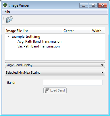
</collector>Path Transmission
The "path transmission" truth collector gathers the average path transmission from the atmosphere within the pixel. Because of the geometric diversity (range, angle, etc.) within a pixel, the average and variance of this parameter is collected:
-
The mean of the bandpass averaged path transmission
-
The variance in the bandpass averaged path transmission
|
|
The average path transmission does not incorporate the relative spectral response (RSR) for each channel. If the user has configured multiple channels for a focal plane, the output truth currently contains the transmission for the entire spectral bandpass sampled for that focal plane. |
|
|
This transmission truth can be used to verify the multiplicative "path" or "upwelled" transmission term extracted from an atmosphere compensation algorithm. |
This truth collector is configured in the .platform file via the following
<collector> syntax:
<collector>
<name>PathTransmission</name>
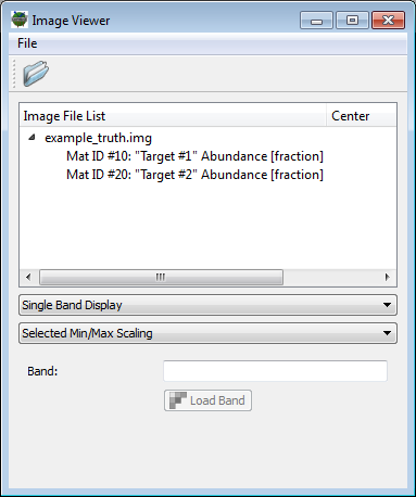
</collector>Abundance
The "abundance" truth collector gathers precise sub-pixel abundance fractions for a user-supplied list of material IDs. This is especially handy in situations where the user is looking to generate a truth mask for a target detection algorithm. The resulting truth "band" for each requested material ID will contain how much of the pixel was occupied by that material or tag as a fraction from 0 - 1. This data can be used to drive pixel resolution receiver operator characteristic (ROC) curve analysis of a target detection algorithm.
The user must supply the truth collector the list of material IDs to be collected as a comma separated list.
|
|
Because the DIRSIG model utilizes ray-tracing, the granularity of the extracted values is subject to sub-pixel sampling. For example, if the user is employing a single sample per pixel, then the collector cannot produce fractional values. The more samples that used per pixel, the better the sampling of the sub-pixel geometry will be and, hence, the more accurate both the radiometry and the truth will be. |
This truth collector is configured in the .platform file via the following
<collector> syntax:
                <collector>
                  <name>Abundance</name>
                  <materials>10,20</materials>
                </collector>
The <materials> element contains the comma separated list of material
IDs for target materials for which sub-pixel abundances will be collected.
Important Notes:
-
In a simulation with multiple-scenes, the abundance collector will find materials with the supplied ID across all scenes. This allows for the abundance of the same material in each scene to be collected into a single truth map.
-
In some cases, scenes might contain materials with the same material ID that were not intended to be same. In those cases, the supplied material ID can be combined with the scene name to only track the material in a specific scene. The format for the material ID in this case is a scene name and material ID pair separated by "
::" (i.e.,tile1::grass, wheretile1is the scene name name andgrassis the material ID).
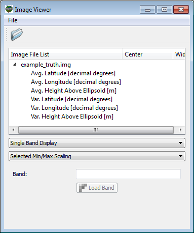
Geolocation
The "geolocation" truth collector gathers the average and variance of the geodetic coordinate for objects within the pixel. The latitude (decimal degrees, positive North), longitude (decimal degrees, positive East) and altitude (meters above the WGS-84 ellipsoid) are collected from all objects intersected within the pixel. The variance in these values will reflect the horizontal and vertical distribution of objects within the pixel.
This truth collector is configured in the .platform file via the following
<collector> syntax:
<collector>
<name>GeoLocation</name>
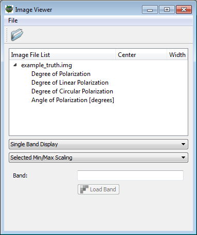
</collector>Polarization
The "polarization" truth collector gathers various degree and angle of polarization quantities for the radiance within the pixel. The following quantities are produced:
-
The degree of polarization (both linear and circular) as a fraction
-
The degree of linear polarization as a fraction
-
The degree of circular polarization as a fraction
-
The angle of linear polarization (in degrees)
|
|
The bandpass integrated Stokes Vector radiances utilized to determine the various quantities do not incorporate the relative spectral response (RSR) for each channel. If the user has configured multiple channels for a focal plane, the output truth currently contains values for the entire spectral bandpass sampled for that focal plane. |
This truth collector is configured in the .platform file via the following
<collector> syntax:
<collector>
<name>Polarization</name>
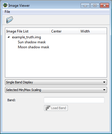
</collector>Shadows
The "shadow" truth collector gathers information about solar and lunar shadows within the pixel.
|
|
Because the DIRSIG model utilizes ray-tracing, the granularity of the extracted values is subject to sub-pixel sampling. For example, if the user is employing a single sample per pixel, then the collector cannot produce fractional values. The more samples that used per pixel, the better the sampling of the sub-pixel geometry will be and, hence, the more accurate both the radiometry and the truth will be. |
This truth collector is configured in the .platform file via the following
<collector> syntax:
                <collector>
                  <name>Shadow</name>
                </collector>
Leaf Area Index
The "leaf area index" truth collector gathers information about the Leaf Area Index (LAI) within the pixel. Since there are multiple definitions of LAI in the general literature, we clarify the definition utilized by DIRSIG here:
|
|
The leaf area index is the ratio of the pixel area to the area of all leaf surfaces within the pixel. For example, a pixel half-filled with a single leaf surface has an LAI of 0.5. A pixel completely filled by a single leaf surface has an LAI = 1.0. A pixel containing two surfaces that each half-fill the pixel also has an LAI = 1.0. A pixel containing two surfaces that each completely fill the pixel has an LAI = 2.0. |
|
|
The LAI calculation does not consider the leaf absorption (transmission) and will include all of the leaf surfaces between the sensor and the ground. Leaf surfaces that are blocked by non-leaf surfaces (branches) are also included in the LAI. |
The user must define which material IDs the truth collector should consider as "leaf" materials. This is provided to the truth collector as a comma separated list.
|
|
Because the DIRSIG model utilizes ray-tracing, the granularity of the extracted values is subject to sub-pixel sampling. For example, if the user is employing a single sample per pixel, then the collector cannot produce fractional values. The more samples that used per pixel, the better the sampling of the sub-pixel geometry will be and, hence, the more accurate both the radiometry and the truth will be. |
This truth collector is configured in the .platform file via the following
<collector> syntax:
                <collector>
                  <name>LeafAreaIndex</name>
                  <materials>1,2,5</materials>
                </collector>
The <materials> element contains the comma separated list of material
IDs for materials to include in the calculation. In this case, the
materials with IDs 1, 2 and 5 correspond to leaf materials.
|
|
To get the LAI of a specific tree species, simply supply the material ID used for that tree leaf. |
Plume/Bulk/Blackadar
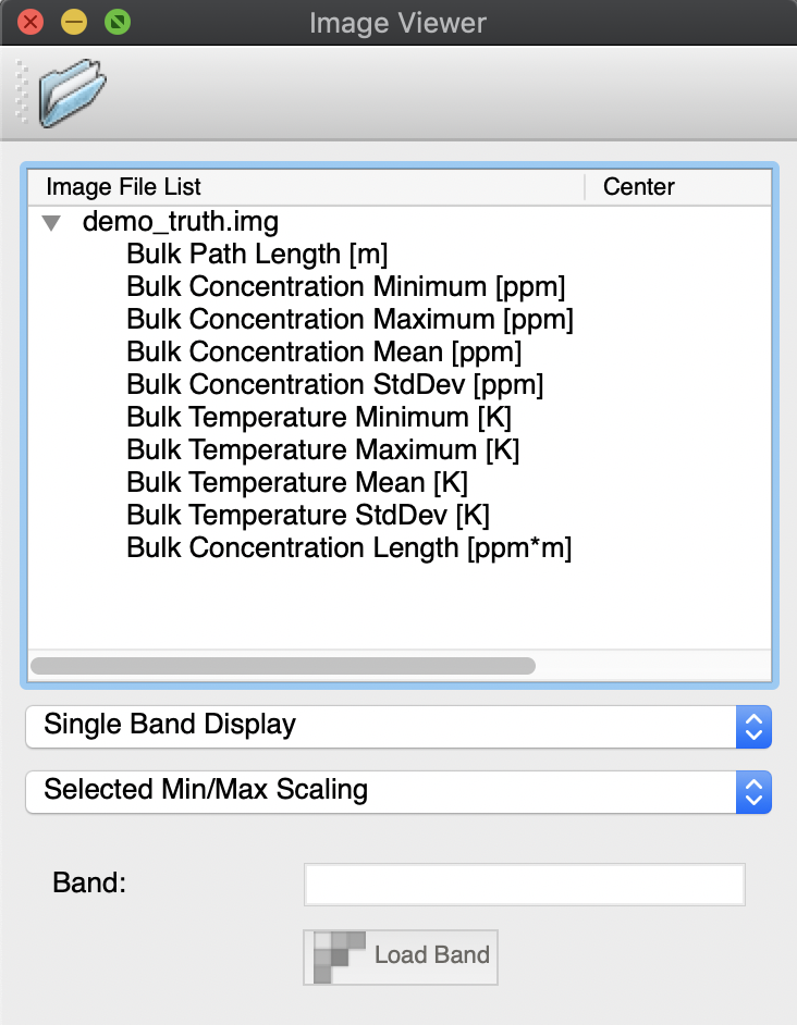
The "plume" truth collector (can also be requested with "bulk" or "blackadar" gathers information about the primary path taken through a plume within the pixel — the length of that path and information about the concentration and temperature along that path. If there are multiple, overlapping bulk materials within a pixel, this truth does not distinguish between them and the overall concentrations and temperatures are provided.
-
The mean path length [m]
-
The minimum, maximum, mean, and standard deviation of concentration [ppm]
-
The minimum, maximum, mean, and standard deviation of temperature [K]
-
The mean concentration length [ppm m]
|
|
If separate plume truth is desired for each bulk material within a pixel, please use the non-raster plume truth which is triggered by an attribute flag to the collector. |
This truth collector is configured in the .platform file via the following
<collector> syntax:
                <collector generate_nonraster_truth="true">
                  <name>Plume</name>
                </collector>
Where the attribute flag has been set to "true" to request non-raster (HDF) truth.
Non-Raster Truth Collectors
Some truth outputs are not well suited for outputting to one or more bands in a rasterized image — usually because the data is sparse or has a varying number of components. In those cases, it is possible to request "non-raster" truth that will be output directly to an HDF file in a convenient format. Both DIRSIG 4 and 5 support certain truth products that can be generated in this way (though not the same ones due to feature support). The general structure of the output is to generate a single HDF file with a group for each non-raster truth being collected.
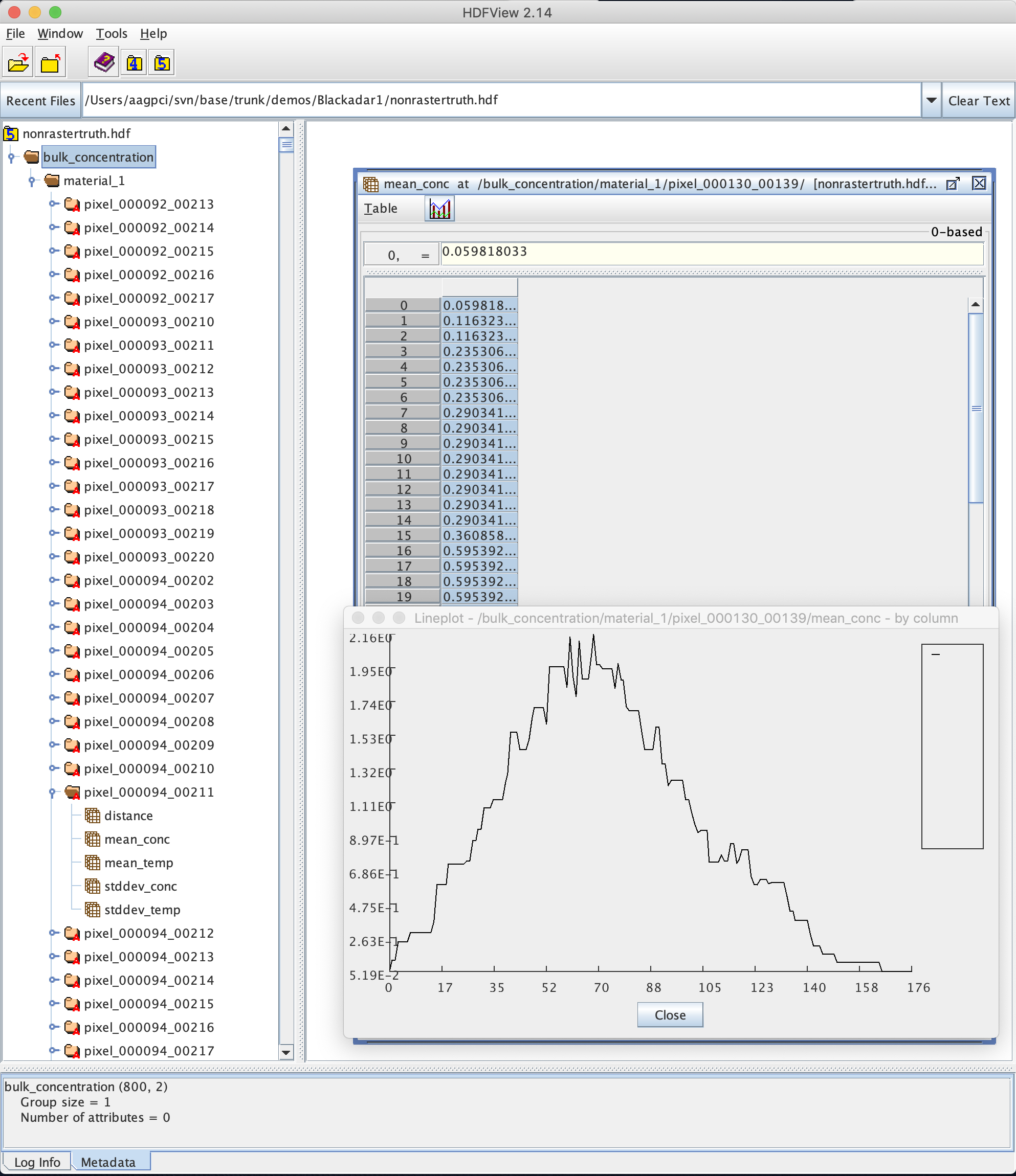
Plume/Bulk/Blackadar non-raster truth (DIRSIG4 only)
The rasterized "plume" truth collector only collects aggregate information about a plume for each pixel in the output truth image(s). The "generate_nonraster_truth" attribute flag (shown previously) allows the user to request detailed information about the concentration and temperature along the path within the plume. Truth data is separated by material in the "bulk_concentration" group and only pixels which had any plume material in it are listed. Additionally, because individual paths can be of different lengths, the exact distance to each sampled value is given in addition to the mean and standard deviation of the concentration [ppm] and temperature [K].
This truth collector is configured in the .platform file via the following
<collector> syntax:
                <collector generate_nonraster_truth="true">
                  <name>Plume</name>
                </collector>
Where the attribute flag has been set to "true" to request non-raster (HDF) truth.