The scene2hdf "scene compiler" was introduced with DIRSIG5 to facilitate
faster start-up times by performing data conversion and checks at a single
point in time rather than as part of each simulation.
With DIRSIG4, the loading of the scene geometry could be a very
slow process if the scene was large and contained a lot of geometry.
This DIRSIG4 compute time was spent performing validity checks on
the scene geometry, the association of geometry to materials, etc.
The realization was that this work was repeated at the start of
every simulation, even if the scene had not changed. With DIRSIG5,
we replaced this frequent and compute intensive task with an
infrequent pre-simulation task. The scene2hdf program included
with DIRSIG5 will "compile" a DIRSIG4 scene into a single, binary
Hierarchical Data Format (HDF)
file that can be quickly loaded and utilized by the DIRSIG5 radiometry
simulation.
This compilation step performs all of these checks on the geometry
and materials once and then allows the DIRSIG5 model to use it
many times. The introduction of this pre-simulation process has
improved scene load times from 10s of minutes to 10s of seconds for
large scenes.
|
|
The user does not need to compile the scene before every simulation. This process only needs to be repeated if the contents of the scene have been modified. |
In early 2021, a ground-up rewrite effort produced a new version of this tool that could compile scenes even faster. In some cases, scenes that used to takes 10s of minutes to compile could now be processed in 10s of seconds. Although scene compilation is supposed to be a process that is performed rarely, these improvements facilitate faster throughput when workflows require frequent scene compilation. When combined with the fast loading of the compiled scenes, the faster scene compilation times greatly reduce the workflow times of DIRSIG5 compared to DIRSIG4.
HDF5 Details
The Hierarchical Data Format (HDF), as the name indicates, is an file container generally used for storing hierarchies of tabulated data. In the case of DIRSIG, these tables include things like the lists of vertexes for a given facetized geometry model, list of parameters for the built-in objects (spheres, cylinders, etc.), lists of static instance transforms for those facet models, list of material properties, collections of curve data, etc. A detailed interface control document (ICD) for the DIRSIG5 scene HDF file can be found here.
|
|
The HDF5 library is distributed with DIRSIG. The library
expects the filesystem to support file locking to avoid
corruption introduced by simultaneous read/write commands.
If your filesystem doesn’t support file locking, then
the HDF5 library will issue an error. The user can
disable HDF5 file locking by setting the environment
variable HDF5_USE_FILE_LOCKING to FALSE.
|
General Usage
To run the scene compiler, you provide the name of the scene file to the program:
.scene file directly.$ scene2hdf my_site.sceneIf a DIRSIG4 simulation file is supplied, the corresponding scene file will be extracted from it:
$ scene2hdf my_demo.simIf a DIRSIG5 JSON simulation file (JSIM) is supplied, the corresponding scene files (there maybe more than one) will be extracted from it and compiled:
$ scene2hdf my_demo.jsimThe scene compiler will then begin the process of reading and checking
all the geometry. It will then produce a file with the same name as the
input .scene file but with .hdf appended to it. From our example
above, the name of the final scene HDF file would be my_site.scene.hdf.
When the tool completes, it will print a series of warnings and (potentially) errors. Most warnings are for currently unsupported features that the tool can work around. Errors arise in situations where the tool cannot find a reasonable work around. Please consult the release notes document for each release for discussions of currently unsupported features and previously unsupported features that are now supported.
Controlling the spectral coverage
One of the tasks of this tool is to minimize the overhead of spectral state changes during the DIRSIG5 run-time, which is partially accomplished by resampling all the scene spectral data to a common set of wavelengths during scene compilation. There are three options to control the spectral resampling when the scene is compiled.
Using the Default Sampling
At this time, the default set of wavelengths is hard-coded to span the visible through short-wave infrared (SWIR) (0.350 - 2.550 microns @ 0.001 micron sampling). This creates problems for users simulating in the mid-wave infrared (MWIR) and long-wave infrared (LWIR) regions, because the scene HDF does not contain spectral reflectance and/or emissivity data for this wavelengths by default. Therefore, it is advised that users utilize one of the following two alternatives.
Using the Scene Modality Properties
The graphical scene editor and scene files now support a way for the user to indicate which common wavelength windows a scene was created for. This allows the user to easily describe the spectral coverage of a scene using these commonly used regions:
-
Ultraviolet (UV, 0.20 - 0.40 microns @ 0.001 microns)
-
Visible (VIS, 0.35 - 0.80 microns @ 0.001 microns)
-
Near Infrared (NIR, 0.70 - 1.40 microns @ 0.001 microns)
-
Short-wave Infrared (SWIR, 1.0 - 2.55 microns @ 0.001 microns)
-
Mid-wave Infrared (MWIR, 2.8 - 5.2 microns @ 0.005 microns)
-
Long-wave Infrared (LWIR, 7.5 - 14.0 microns @ 0.005 microns)
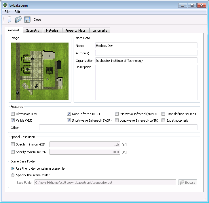
The scene compiler will resolve overlaps in these pre-defined spectral windows. These windows can be selected in the graphical scene editor on the General tab (see below):
They can also be specified in the .scene file via the features
attribute in the <properties> element:
<classicscene>
  ...
  <properties features="uv,vis,nir,swir,mwir,lwir"/>
  ...
</classicscene>
Please note that all of the corresponding window names are provided in the example above. The scene builder should only specify wavelength windows for which the scene has valid spectral data.
Using a Spectral Samples File
To override the default spectral sampling used by the scene compiler,
the user needs to create a file that contains a list of wavelengths to be used
for spectral resampling at scene compilation time. This file is then passed to
scene2hdf through the --spectral_samples command line option.
|
|
Using a spectral samples file overrides the sampling defined by the
.scene file modality properties described above. This is an
advanced feature that is only recommended for edge cases, not for
general use.
|
The file starts with microns (other supported units include nanometers
and wavenumbers) and then includes a list of arbitrary wavelengths.
These wavelengths do not need to be regularly spaced.
microns
0.4
0.41
0.42
[lines deleted for documentation purposes]
11.90
11.95
12.00
|
|
If a user combines a sensor plugin and a scene HDF that do not have overlapping spectral coverage, an error will be issued by DIRSIG. |
Command-Line Options
The scene2hdf tool usage message summarizes the available options:
$ scene2hdf -h
Usage: scene2hdf [options] filename

Compiler for DIRSIG5 scene HDF files.

Positional Arguments:
  filename (required!)
	The input filename (.jsim, .sim, .scene).

Options:
  -h/--help
	Display this help and exit.
  -v/--version
	Display build and version info and exit.
  --log_level string
	Sets the minimum logging level (debug, info, warning, error, critical, off). Defaults to info.
  --random_seed uint
	The random seed.
  --reference_date_time string
	The reference date/time (IS0-8601 string) for relative times.
  --spectral_samples string
	Advanced: The filename for a spectral samples file (override for <properties> in .scene file)
  --default_time_interval float float
	The default time interval to use for estimating dynamic instance bounds. If not present, no dynamic instance bounds are considered.
  --skip_unused_materials
	Advanced: Skip unused materials by possibly compiling the scene twice. Note that this may double the compile time, so use sparingly.
  --purge_sqt_cache
	Advanced: Purge the SQT cache and exit.
Controlling console message verbosity
The --log_level option allows the user to change the verbosity of the
output produced by the tool. The available log levels are those supported
by the spdlog library:
-
off(no output) -
critical(only critical errors) -
error(only critical and non-critical errors) -
warning(only warnings and errors) -
info(the default) -
debug(more verbose than the default) -
trace(unavailable in releases, reverts todebug)
The default is the info level, which provides minimal messages while
the scene is compiled. To gain more insights into the details of the
compilation process, you can increase the verbosity of the tool by
requesting the debug output:
$ scene2hdf --log_level=debug my_demo.sceneTo reduce the output of the tool, you can change the log level by moving
in the opposite direction (warning, error, etc.) all the way to the
off level which will produce no console output.
Purging the SQT cache
The tool attempts to minimize the execution of computationally expensive
tasks by caching results when possible. One of these caches is the SQT
cache, which stores SQT files for scenes from previous compilation runs.
The default cache is located in the user’s Documents/DIRSIG/cache
folder, and will contain a series of files with the .sqt extension.
The main part of the filename is a hash created from the input files and
data for the BRDF that was captured by this SQT file. In some situations,
it is desirable to purge this cache and force the scene compiler to
compute new SQT fits. In those situations, you can either manually
remove the files in the cache folder or use the --purge_sqt_cache
option:
$ scene2hdf --purge_sqt_cache|
|
This option will pay attention to the DIRSIG_CACHE_DIR variable
described here.
|
Skipping unused materials
By default, the compiler incorporates all of the materials defined in the scene and bundle material files. In most cases, the addition of "unused materials" (materials that are not referenced by any geometry in the scene) is harmless. However, in some configurations users might find that the inclusion of unused materials results in undesired storage requirements (the compiled HDF file is much larger than it needs to be). To address this, the compiler can be run in a two pass mode, where the first pass collects a list of unused materials and the second pass performs the final compilation where these unused materials are skipped.
|
|
Engaging this option will nearly double the compilation time, but since scene compilation is intended to be a rarely performed task, the benefit of a smaller compiled scene HDF might be worth the computational cost. |
--skip_unused_materials option.$ scene2hdf --skip_unused_materials big_scene.sceneOther Options
Overriding the cache directory
The default location of the DIRSIG cache directory is assumed to be the
user’s Documents/DIRSIG/cache folder. If the user wishes to
use an alternative location, the DIRSIG_CACHE_DIR environment variable
can be set to specify an alternative directory.
Additional Output
Material Report
The JSON file material_report.json is produced as part of the the scene
compilation process. The importance of this file is that it allows the
user to associate the material index truth with
a material identity (label/ID and name). Below is the report for the
Brdf1 demo:
{
  "info": {
    "created": "2021-03-30 09:41:22",
    "file_type": "Material Report",
    "generator": "scene2hdf",
    "version": "2021.13 (80483d2)"
  },
  "materials": {
    "bundles": [],
    "scene": {
      "10": {
        "materialIndex": 2,
        "name": "60% Lambertian, White (id = 10)"
      },
      "11": {
        "materialIndex": 3,
        "name": "0% Lambertian, Black (id = 11)"
      },
      "2": {
        "materialIndex": 1,
        "name": "Perfect Reflector (id = 2)"
      },
      "500": {
        "materialIndex": 4,
        "name": "Glossy red paint, version 1 (id = 500)"
      },
      "510": {
        "materialIndex": 5,
        "name": "Glossy red paint, version 2 (id = 510)"
      },
      "520": {
        "materialIndex": 6,
        "name": "Glossy red paint, version 3 (id = 520)"
      },
      "600": {
        "materialIndex": 7,
        "name": "Gold, shiny (id = 600)"
      },
      "610": {
        "materialIndex": 8,
        "name": "Gold, slightly dull (id = 610)"
      }
    }
  }
}
If the material truth image indicates material index 4 is associated with
a surface, the user will find the entry with the materialIndex of 4:
      "500": {
        "materialIndex": 4,
        "name": "Glossy red paint, version 1 (id = 500)"
      },
This material is the glossy red paint found in the scene material file,
with the ID = 500.
If the scene leverages any bundled objects, the bundles array will be
populated with information for materials specific to each bundle. Although
the material labels (aka the ID values) do not need to be unique across
bundles, the material indexes are global to entire scene and unique. Below
is the material_report.json for the
BundledObject1 demo:
{
  "info": {
    "created": "2021-03-30 10:57:24",
    "file_type": "Material Report",
    "generator": "scene2hdf",
    "version": "2021.13 (80483d2)"
  },
  "materials": {
    "bundles": [
      {
        "filename": "/Users/dirsig/tmp/BundledObject1/geometry/bundles/infiniti_g35/infiniti_g35.glist",
        "materials": {
          "1": {
            "materialIndex": 4,
            "name": "Gloss paint, blue (id = 1)"
          },
          "2": {
            "materialIndex": 5,
            "name": "Glass (id = 2)"
          },
          "3": {
            "materialIndex": 6,
            "name": "Chrome (id = 3)"
          },
          "4": {
            "materialIndex": 7,
            "name": "Tire, Rubber, Black, Fair (id = 4)"
          },
          "5": {
            "materialIndex": 8,
            "name": "Vinyl, tan (id = 5)"
          }
        },
        "objectIndex": 0
      },
      {
        "filename": "/Users/dirsig/tmp/BundledObject1/geometry/bundles/parking_lot/parking_lot.glist",
        "materials": {
          "1": {
            "materialIndex": 3,
            "name": "Parking lot, base (remapped) (id = 1)"
          },
          "2": {
            "materialIndex": 1,
            "name": "Roadway Surfaces, Asphalt, Old, Gray (id = 2)"
          },
          "3": {
            "materialIndex": 2,
            "name": "Roadway Surfaces, Asphalt, Old, Gray, lines (id = 3)"
          }
        },
        "objectIndex": 0
      }
    ],
    "scene": {}
  }
}
In this case, you can see that material index 2 is the road defined in
the "parking lot" bundle and material index 7 is the rubber tire defined
in the Infinity G35 bundle.
Asset Report
The tool also produces the asset_report.txt file, which is an
ASCII/Text file that contains a list of all the input files that were
read during the scene loading process. Each line contains the
filename, the modification date and the size of the file. The last
line of the file contains an MD5 hash created from the contents of
all the input files.
Below is an example asset_report.txt for the
Brdf1 demo:
demo.scene,2020-09-14T10:54:20,1703
geometry/background.glist,2020-09-14T10:54:20,305
geometry/objects.glist,2020-09-14T10:54:20,9126
materials/brdf/au.fit,2020-09-14T10:54:24,4010
materials/brdf/aud.fit,2020-09-14T10:54:24,4000
materials/brdf/gloss.fit,2020-09-14T10:54:24,841
materials/demo.mat,2020-09-14T10:54:24,3163
materials/emissivity/au.ems,2020-09-14T10:54:24,233
materials/emissivity/red_panel.ems,2020-09-14T10:54:24,1114
MD5 hash = bc85532022364db47a83893d35eb7160
Important Notes:
-
The list of files in the report only includes files that are used in the scene. Files that are not used in the scene are not included in the listing or the MD5 hash. Hence, this file listing can be used to create the definitive list of files used in a given scene folder. By extension, the list can be used to relocate/remove unused files that are cluttering up a given scene.
-
The MD5 hash will only change if one (or more) of the files in the scene is changed. Hence, it can be used to compare two copies of a scene to confirm if they are a match or not. If the MD5 hash is the same, the various scene files can be assumed to match. If they hash is not the same, the file listing, modification dates and file sizes can be used to identify which files differ.
-
If all you have is the compiled scene HDF file, this information is also stored in the
/Info/GeneratorData/Assetsgroup within the scene HDF file.