The GenericMotion model was originally introduced to describe
platform motion, hence it’s associated platform position data (PPD)
file (commonly seen with the .ppd file extension). A PPD file
contains a series of records that indicate the platform’s position
and orientation as a function of time. This file is an XML formatted
file which makes it easier and more reliable to parse and allows
the data to be authored and viewed in other software packages.
Reference Frame
The primary coordinate system in DIRSIG is the East-North-Up (ENU), where the ENU axes correlate to X, Y and Z, respectively. The reference frame for motion models in DIRSIG is as follows:
-
The "forward" axis is the +Y axis.
-
The "up" axis is the +Z axis.
-
The remaining axis (+X) is the "right" wing (follows the right-hand rule).
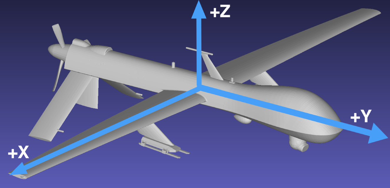
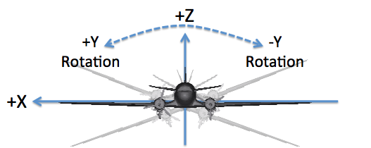
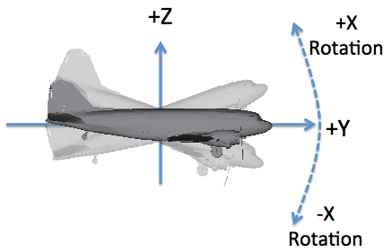
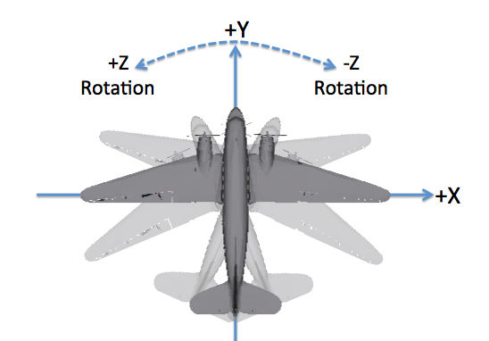
How do roll, pitch and yaw relate to this motion frame?
-
The "roll" axis is Y, and a positive angle corresponds to a right wing down or left wing up rotation.
-
The "pitch" axis is X, and a positive angle corresponds to a "nose up" rotation.
-
The "yaw" axis is Z, and a positive angle corresponds to a counter-clockwise rotation as viewed from above.
|
|
The DIN 9300 and ISO 1151–2 conventions also follow a right-hand rule but define the +X axis as the "forward" or "roll" axis, the +Y axis as the "right wing" or "pitch" axis and the +Z axis as the "down" or "yaw" axis. Special care must be taken to know which convention is being used when rotation data is being imported. |
|
|
The motion defines the location and orientation of the object it is associated with. For platform motion in sensor plugins it is important to know what the default camera orientation is relative to the vehicle. For example, in the BasicPlatform plugin the default orientation of cameras is looking down the -Z axis. |
Reference Sequences
In addition to knowing what the reference axes are, you must know if the rotations are used as part of an extrinsic or intrinsic sequence:
- extrinsic
-
Every rotation in a sequence is relative to a global coordinate system.
- intrinsic
-
A rotation in a sequence refers to the last rotated coordinate system, with the first rotation relative to the global coordinate system.
|
|
The various motion models support interpreting Euler angles as either an extrinsic or intrinsic rotation sequence. Some motion models support selecting between extrinsic or intrinsic sequences while others are hard-coded to support only one or the other. |
This motion model supports either extrinsic or intrinsic sequences.
See the <rotationframe> attribute to know which convention is used.
Jitter
Jitter can be independently configured for each of the three primary axes
(X, Y and Z) for both the location and orientation, or a total of six
degrees of freedom (DoF). The location and orientation (rotation) jitter
configurations are (optionally) introduced via the <locationjitter>
and/or <orientationjitter> elements. The configuration of the models
is consistent between the location and orientation, with the units of
the magnitudes being the primary difference. The location and orientation
models will expect magnitudes in meters and radians, respectively.
  <locationjitter>
    <xaxis type="normal">
      <values magnitudeunits="meters">
        <mean>0</mean>
        <standarddeviation>0.1</standarddeviation>
      </values>
    </xaxis>
  </locationjitter>
  <orientationjitter>
    <zaxis type="normal">
      <psd frequencyunits="hertz" magnitudeunits="radians">
        <entry>
          <frequency>2</frequency>
          <magnitude>0.5</magnitude>
          <phase>0</phase>
        </entry>
      </psd>
    </zaxis>
  </orientationjitter>
The jitter configuration for each axis can be uniquely defined via a
<xaxis>, <yaxis> and <zaxis> element in the respective
<locationjitter> and <orientationjitter> elements. Not defining
the configuration for an axis means that no deviations will be introduced
for that axis.
Uncorrelated Jitter
The temporally uncorrelated model is completely random as a function of time. The model is configured with a mean and standard deviation to drive the uniformly distributed deviations.
    <xaxis type="normal">
      <values magnitudeunits="meters">
        <mean>0</mean>
        <standarddeviation>0.1</standarddeviation>
      </values>
    </xaxis>
Correlated Jitter
The temporally correlated model leverages a power spectral density (PSD)
or frequency spectrum to synthesize deviations that are correlated with
time. Each frequency mode is described by an <entry> in the <psd>
element, which includes the magnitude and phase for a given frequency.
    <xaxis type="correlated">
      <psd frequencyunits="hertz" magnitudeunits="radians">
        <entry>
          <frequency>2</frequency>
          <magnitude>0.5</magnitude>
          <phase>0</phase>
        </entry>
        <entry>
          <frequency>10</frequency>
          <magnitude>0.2</magnitude>
          <phase>0</phase>
        </entry>
      </psd>
</xaxis>|
|
The deviation for a given point in time is brute force computed by
evaluating the magnitude of each frequency mode described. Hence,
it is more efficient to not include frequencies with a magnitude of
0.
|
Format Details
There are two generations of the XML schema that can appear in a PPD file. The older format only supported the Scene ENU coordinate system, while the newer format supports use of the Scene ENU coordinate system as well as absolute geographic coordinates (see the Coordinates Manual for more information). Regardless of the "new" vs. "old" format, the top level elements of the XML hierarchy are the same:
<platformmotion type="generic">
  <method type="raw"></method>

  <locationjitter>
  </locationjitter>

  <orientationjitter>
  </orientationjitter>

  <data ... >
    <entry>
      ...
      [lines deleted for documentation purposes]
      ...
    </entry>
    ...
    <entry>
      ...
    </entry>
  </data>
</platformmotion>
The "generic" platform model is chosen by supplying the name "generic"
in the type attribute.
The next element is the <method> is reserved for future expansion
when the method and parameters used to generate specific platform
positioning and pointing data will be stored here. For now, the
type attribute for the method expects to see "raw" which is an
free-style method that is used to describe any other means used to
create the data (including hand generated data or data imported
from other sources).
The differences between the "new" vs. "old" formats are isolated to
the <data> section, which describes the platform position and
orientation as a function of time. This is achieved through a
sequence of <entry> elements
Common Conventions
Although the format of the <entry> elements in the "new" vs. "old"
files varies, there are common conventions used in both. In general,
each entry provides the data to construct an affine
transform describing the location and orientation of the platform
as a function of time.
Time
Each <entry> contains a <datetime> element that defines the
relative time for this entry. This time is relative to the Reference
Date/Time define in the .tasks file employed by the simulation.
At this time, only relative times are supported (absolute date/time
will be added at a later point).
|
|
The list of <entry> elements describe the position and
orientation of the platform at specific points in time.
If DIRSIG needs to know the location and orientation for
an intermediate time, the values are linearly interpolated
from the adjacent times.
|
Rotations
The <data> element has an attribute called rotationorder that is
assigned a 3-character string defining the order that the X, Y and Z
rotations are applied. For example, the string xyz means that the
axis rotations are applied in the order "X, then Y, then Z".
|
|
The order of rotations is important. The final orientation can be dramatically different if the order that rotations are applied is changed (see the affine transform documentation for an explanation). |
|
|
The most common rotation order for a "roll, pitch and yaw"
description is "roll, then pitch, then yaw", which would be a
rotation order of yxz for a DIRSIG plaform.
|
Older Data Format
Below is an example of an older XML position/orientation data file
for the "generic" platform motion model. The position and orientation
of the platform as a function of time is defined by a sequence of
<entry> elements:
<platformmotion type="generic>
  <method type="raw" />
  <data rotationorder="xyz">
    <entry>
      <datetime type="relative">0.000</datetime>
      <xlocation>0</xlocation>
      <ylocation>0</ylocation>
      <zlocation>1000</zlocation>
      <xrotation>0.00000</xrotation>
      <yrotation>0.00000</yrotation>
      <zrotation>0.00000</zrotation>
    </entry>
  </data>
</platformmotion>
The rotationorder attribute in the <data> element defines the order
that the X, Y and Z rotations are combined. This string will be some
permutation of the string "xyz" indicating Euler angle rotation order.
Each axis is expected to appear exactly once in the string. A value of
"xyz" means first about X-axis, then the Y-Axis and then the Z-axis.
The xlocation, ylocation and zlocation variables define the
XYZ location of the platform in meters in the Scene ENU coordinate
system.
The xrotation, yrotation and zrotation variables define
the XYZ rotation angles about the respective Scene ENU axis
in radians.
Newer Data Format
The newer <data> format added support for geographic coordinate systems.
To support this flexibility, a series of new XML attributes were added to
the <data> element:
<platformmotion type="generic">
  <method type="raw" />
  <data rotationframe="sceneenu" rotationorder="xyz" angletype="absolute" angularunits="radians" spatialunits="meters">
    <entry>
      <datetime type="relative">0</datetime>
      <position>
        <scenelocation>
          <point><x>0.000</x><y>0.000</y><z>1000.000</z></point>
        </scenelocation>
      </position>
      <orientation>
        <eulerangles>
          <cartesiantriple><x>0.000</x><y>0.000</y><z>0.000</z></cartesiantriple>
        </eulerangles>
      </orientation>
    </entry>
  </data>
</platformmotion>
These <data> element attributes are defined as follows:
rotationframe-
The reference frame for orientation vectors, which can be:
-
Scene relative East-North-Up (
"sceneenu", angles are interpreted as extrinsic), -
Earth-Centered, Earth-Fixed (
"ecef", angles are interpreted as extrinsic), or -
Platform relative XYZ (
"platformxyz"or"platformenu", angles are interpreted as intrinsic).
-
rotationorder-
The order in which orientation Euler rotations are applied. The order "xyz" indicates to first rotate around the X-axis, then the Y-axis, then the Z-axis. Arbitrary combinations of the three axes are allowed, such as "zyx" and "yxz". See the Affine Transform document for a more detailed explanation.
angletype-
Currently only the
"absolute"is supported, which indicates that orientation Euler rotations are relative to the vectors (0,0,-1) and (0,1,0) in the specified"rotationframe". angularunits-
The units used for rotations. Only
"radians"is currently supported. spatialunits-
The units used for Scene ENU (local) coordinate positioning. Only
"meters"is currently supported.
Each <entry> contains a <position> and an <orientation> element.
Depending on the reference coordinate system, reference rotation frame,
etc. the entries will contain different data.
Scene ENU Position
Support for Scene-ENU coordinate systems for the position are supported via
the <scenelocation> element:
      <position>
        <scenelocation>
          <point><x>600</x><y>600</y><z>1200</z></point>
        </scenelocation>
      </position>
Geodetic Position
Support for geodetic coordinate systems for the position are provided via
the <geodeticlocation> element:
      <position>
        <geodeticlocation>
          <latitude>43.120</latitude>
          <longitude>-78.450</longitude>
          <altitude>1500.000</altitude>
        </geodeticlocation>
      </position>
Or via the updated <location> format introduced in DIRSIG 4.5.0:
      <position>
        <location frame="geodetic">
          <latitude>43.120</latitude>
          <longitude>-78.450</longitude>
          <altitude>1500.000</altitude>
        </location>
      </position>
UTM Position
Support for UTM coordinate systems for the position are provided via
the <utmlocation> element:
      <position>
        <utmlocation>
          <zone>17</zone>
          <hemisphere>N</hemisphere>
          <easting>707445.963</easting>
          <northing>4777297.178</northing>
          <altitude>1500.000</altitude>
        </utmlocation>
      </position>
Or via the updated <location> format introduced in DIRSIG 4.5.0:
      <position>
        <location frame="utm">
          <zone>17</zone>
          <hemisphere>N</hemisphere>
          <easting>707445.963</easting>
          <northing>4777297.178</northing>
          <altitude>1500.000</altitude>
        </location>
      </position>
ECEF Position
Support for ECEF coordinate systems for the position are provided via
the <eceflocation> element:
      <position>
        <eceflocation>
          <point><x>933829.296</x><y>-4569502.813</y><z>4338267.397</z></point>
        </eceflocation>
      </position>
Or via the updated <location> format introduced in DIRSIG 4.5.0:
      <position>
        <location frame="ecef">
          <x>933829.296</x>
          <y>-4569502.813</y>
          <z>4338267.397</z>
        </location>
      </position>
Orientation
The orientation data for a given <entry> is limited to a triplet of
Euler rotation angles:
      <orientation>
        <eulerangles>
          <cartesiantriple><x>0</x><y>0</y><z>-5.06145483</z></cartesiantriple>
        </eulerangles>
      </orientation>
The order that these angles are combined is defined by the rotationorder
attribute in the <data> element. The reference coordinate system for
these angles is defined by the rotationframe attribute.