The DIRSIG model supports full geolocation of scene elements and the platform. This support allows the scenes to be located at some well defined place on the planet. It also allows the platform to be placed using the geographical coordinate systems that are commonly used by flight data recorders and mission planning software packages. The following coordinate systems can be used to position any DIRSIG scene element or platform:
-
The Scene East-North-Up (Scene ENU) coordinate system
-
The Geodetic (Latitude/Longitude) coordinate system
-
The Universal Transverse Mercator (UTM) coordinate system
-
The Earth-Centered, Earth-Fixed (ECEF) coordinate system
The DIRSIG model allows the user to specify the location of an object using any of the supported coordinate systems. That means a given simulation may have a mix of scene elements that are located using one or more geographic coordinate systems and a platform using yet another. Since a Cartesian coordinate system is required in order to perform basic Euclidean mathematics required for ray tracing an other geometric calculations, the DIRSIG model automatically constructs an internal Cartesian coordinate system and translates all geographic coordinates into it.
|
|
All geographic transforms are performed using
GeographicLib. See the
license info using dirsig --licenses command-line option.
|
|
|
At this time all geographic altitudes supplied to DIRSIG are assumed to be with respect to the WGS84 datum. There is not a way to specify an alternate datum at this time. |
Although a scene is assembled using a variety of objects which can be placed using both geographic and arbitrary coordinate systems, any object has an effective geographic location.
The Scene East-North-Up (Scene ENU) Coordinate System
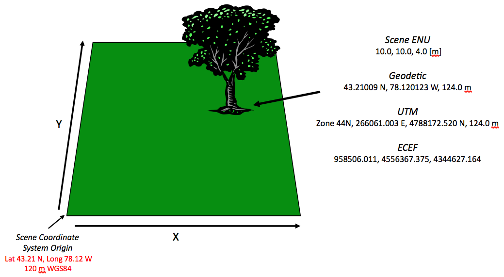
The "scene" or "local" coordinate system is the most basic coordinate system. The "scene" coordinate system is essentially an arbitrary, Cartesian coordinate system. By definition, the coordinate system is a "flat earth" system that uses linear X, Y and Z coordinates to locate elements with respect to the coordinate systems origin. This coordinate system is best used for smaller area extents where the curvature of the earth is not a concern (less than 4 km).
Although the coordinate system is itself arbitrary, the "scene" coordinate system still supports geolocation because the origin of this arbitrary coordinate system is tied to a geolocation. When translated to this geolocated "tie point", the scene +Y axis corresponds to North and the scene +X corresponds to East. This makes the scene coordinate system an "East North Up" (ENU) coordinate system.
Because the scene coordinate system assumes a flat earth, it is not a good coordinate system to use over large distances. For example, unless your platform is directly overhead, using the scene coordinate system for a high altitude or space-based platform would not be suggested. However, it is a convenient coordinate system for small areas because it allows for the use of Euclidean geometry.
|
|
Another common coordinate system is North-East-Down (NED), where X corresponds to North, Y corresponds to East and Z is down. Note that like ENU this is still a right-handed coordinate system. To convert from one to the other (ENU → NED or NED → ENU), swap X and Y and negate Z. |
The Geodetic (Lat/Long) Coordinate System
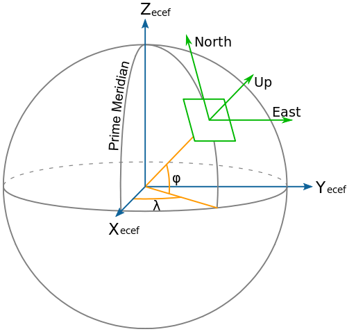
The "geodetic" coordinate system is known to most as the "Latitude and Longitude" coordinate system. The geodetic grid for the planet is comprised of parallel East/West lines of latitude and North/South lines of longitude that intersect at the poles. Latitude and longitude lines are labeled by the angle they subtend with respect to a reference. For latitude, that 0 reference is the Equator and for longitude that 0 reference is the Prime Meridian.
Since the longitude lines are not parallel, the horizontal distance for a degree of longitude depends on your location. Therefore, the geodetic location does not have intuitive understanding of distance that other coordinate systems have. However, the geodetic coordinate system is globally consistent and therefore is a good coordinate system for positioning high altitude and space-based platforms.
In DIRSIG 4.5.0, the new <location> schema was introduced to
describe a location in a DIRSIG input file. The following is
an example of a geodetic coordinate:
        <location frame="geodetic">
          <latitude>43.120</latitude>
          <longitude>-78.450</longitude>
          <altitude>1500.000</altitude>
        </location>
The Universal Transverse Mercator (UTM) Coordinate System
The Universal Transverse Mercator (UTM) coordinate system is a geographic coordinate system which utilizes a conformal projection that preserves angles locally. This is achieved by breaking the entire globe into a sequence of small conformal projections. These local projections are called "grid zones" which are defined by a longitude "zone" (the earth is divided into 60 zones, each 6 degrees wide and number sequentially) and a latitude "band" (the earth is divided into 20 latitude bands, each 8 degrees wide and labeled with a lettering scheme). The horizontal location offsets within a given grid zone are referred to as the "Easting" and "Northing" and are generally measured in meters.
The key advantage of the UTM coordinate system is that distances and angles can be computed using Euclidean geometry over short distances. This makes is very easy to compute distances and angles. And coordinate units are in meters, making the coordinates intuitive to interpret. However, the UTM projections suffer from ambiguities at the meeting of two grids zones and general distortions for large areas and distances. Although UTM could be used to position a plane or satellite, as it moved from one grid zone to another, the relative position will be prone to errors.
In DIRSIG 4.5.0, the new <location> schema was introduced to
describe a location in a DIRSIG input file. The following is
an example of a UTM coordinate:
        <location frame="utm">
          <zone>17</zone>
          <hemisphere>N</hemisphere>
          <easting>707445.963</easting>
          <northing>4777297.178</northing>
          <altitude>1500.000</altitude>
        </location>
The Earth-Centered, Earth-Fixed (ECEF) Coordinate System
The Earth-Centered, Earth-Fixed (ECEF) coordinate system is also known as the "conventional terrestrial" coordinate system. It is a simple Cartesian coordinate system with the center of the earth at it’s origin. The +X axis passes through the Equator and Prime Meridian intersection. The +Z axis passes through the North Pole. The +Y axis is orthogonal to +X and +Z. As a result, this coordinate system rotates with the earth. The distances used along each axis are meters.
Since the entire ECEF reference frame rotates with the earth, this coordinate system is useful for positioning geo-stationary objects such as satellites. In fact, the Global Positioning System (GPS) uses ECEF as it’s primary coordinate system and derives all other coordinates from it. However, since ECEF has an origin that is very far from most locations on the surface of the earth, it would be awkward for a small scene with a platform located at a small distance away because all the coordinates will be biased by the large offset to the center of the earth.
In DIRSIG 4.5.0, the new <location> schema was introduced to
describe a location in a DIRSIG input file. The following is
an example of an ECEF coordinate:
        <location frame="ecef">
          <x>933829.296</x>
          <y>-4569502.813</y>
          <z>4338267.397</z>
        </location>
Choosing a Coordinate System
The choice of a coordinate system is dependent on a host of variables. However, the choice of which coordinate system to use can be customized based on the element to be positioned. It is important to recognize that the inherently geolocated coordinate systems do not have an advantage over the scene coordinate system. For example, do not feel compelled to use a geolocated coordinate system for positioning scene elements because you fear that it will limit what coordinate system you plan on using for the platform positioning. DIRSIG will automatically establish an internal coordinate system for your simulation and translate all coordinates into and out of it. Therefore, the first rule is to use whatever is most convenient (e.g. "use what you have"). Consider the following general recommendations.
Positioning Scene Elements
Since most CAD programs, etc. work in a Cartesian coordinate system using the "Scene" coordinate system is very natural. The key suggestion is to recognize that this coordinate system will be translated to a geo-located one assuming an "East North Up" (ENU) convention. Therefore, make sure you use the X/Y axis as surrogates for East/North and avoid the need to rotate your scene into the global geolocated coordinate system.
However, if you are creating a DIRSIG scene of a real world location and you have survey points for the locations of all the objects in your scene, then it would be silly not to use them directly. Furthermore, it will be silly to translate them into another coordinate system for no apparent reason. Therefore, the obvious rule of "use what you have" should be considered.
|
|
The advantage to using Scene ENU for scene construction is that the entire scene can be quickly relocated by simply changing the geographic location corresponding to the Scene ENU origin. If an absolute geographic coordinate is used to position every object, then every object needs to be modified to relocate the scene. |
Positioning a Local Camera
The key suggestion would be to use the same coordinate system as the scene to make the relative positioning of the camera easy.
Positioning an Airborne Platform
If you are using flight recorder data from a real aircraft, then use the coordinate system that the flight data was recorded with. The platform motion editor tool has import tools that will assist you in ingesting the Geodetic, UTM, etc. data into the simulation.
Positioning a Low Earth Orbit (LEO) Platform
Geodetic coordinates are probably the best choice for a LEO platform. This coordinate system allows the platform to be correctly positioned anywhere. In contrast, using the ECEF coordinate system would require the user to back out the earth rotation from the platform position since both are moving at different rates.
Positioning a Geo-Synchronous Platform
The ECEF coordinate system is ideal in this situation. Since the platform is rotating in sync with the earth, then the ECEF coordinate of the platform is constant.
FAQ
- What do X/Y mean in the world coordinate system?
-
"If I am flying along the Y axis, what does that mean?" DIRSIG’s native coordinate system is the "Scene ENU" coordinate system, where ENU is short for East-North-Up. That translates to +X is East, +Y is North and +Z is up. If you have a sequence of increasing Y locations in a PPD file, an ODB file, a GLIST file or a MOV file then that sequence of locations is "headed" north.
- What is the nominal orientation of the platform?
-
"If a PPD file has
0for all the orientation angles, what does that mean?" By default, the +Y Axis is the nominal along-track axis and a camera mounted to a platform is pointed down (-Z). Therefore, if you have a positive Z rotation, then that is "yaw" in a counter-clockwise direction as viewed from above. If you have some Y rotation, that is "roll" and if you have some X rotation then that is some "pitch". However, these are Euler angles and there is the concept of order of rotation. If you rotate about Z and then Y, that is VERY different than doing the same rotations in the order Y and then Z (see the Affine Transform document for a more detailed explanation). Also, remember that each instrument is attached to the platform through a sequence of attachment and mount transforms. Therefore, the X-axis of an instrument is not always across-track with respect to the platform because the instrument could be rotated relative to the platform.
Credits
-
The Geodetic/ECEF/SceneENU figure is courtesy of Wikipedia and is available for public domain usage.