Overview
This document describes the Flexible motion model that enhances the capabilities to model moving scene objects and imaging platforms in DIRSIG. The driving design concept is to split the calculations into a separate location calculation (which defines where an object is located) and orientation calculation (which defines how an object is oriented). By doing so, we can implement a suite of simpler calculations or "engines" for each component. The user can then configure different types of scenarios by creating different combinations of these location and orientation engines.
It is expected that future feature enhancements to motion will be accomplished by improving existing or adding new engines to this model. The older motion models (GenericMotion and DeltaMotion) will be maintained to provide backward support even though they could be replaced by some combination of engines within this new model.
Reference Frame
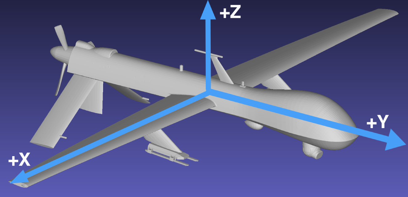
The primary coordinate system in DIRSIG is the East-North-Up (ENU), where the ENU axes correlate to X, Y and Z, respectively. The reference frame for motion models in DIRSIG is as follows:
-
The "forward" axis is the +Y axis.
-
The "up" axis is the +Z axis.
-
The remaining axis (+X) is the "right" wing (follows the right-hand rule).
How do roll, pitch and yaw relate to this motion frame?
-
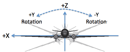
The "roll" axis is Y, and a positive angle corresponds to a right wing down or left wing up rotation.
-
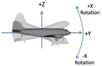
The "pitch" axis is X, and a positive angle corresponds to a "nose up" rotation.
-
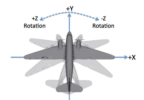
The "yaw" axis is Z, and a positive angle corresponds to a counter-clockwise rotation as viewed from above.
|
|
The DIN 9300 and ISO 1151–2 conventions also follow a right-hand rule but define the +X axis as the "forward" or "roll" axis, the +Y axis as the "right wing" or "pitch" axis and the +Z axis as the "down" or "yaw" axis. Special care must be taken to know which convention is being used when rotation data is being imported. |
|
|
The motion defines the location and orientation of the object it is associated with. For platform motion in sensor plugins it is important to know what the default camera orientation is relative to the vehicle. For example, in the BasicPlatform plugin the default orientation of cameras is looking down the -Z axis. |
Most of the location and orientation (rotation) engines have a user
supplied reference coordinate system or "frame", that is usually
supplied as an attribute to the XML element. This frame attribute
defines what coordinate system the location or orientation (rotation)
the definition is in reference to.
Jitter
Jitter can be independently configured for each of the three primary axes
(X, Y and Z) for both the location and orientation, or a total of six
degrees of freedom (DoF). The location and orientation (rotation) jitter
configurations are (optionally) introduced via the <locationjitter>
and/or <orientationjitter> elements. The configuration of the models
is consistent between the location and orientation, with the units of
the magnitudes being the primary difference. The location and orientation
models will expect magnitudes in meters and radians, respectively.
  <locationjitter>
    <xaxis type="normal">
      <values magnitudeunits="meters">
        <mean>0</mean>
        <standarddeviation>0.1</standarddeviation>
      </values>
    </xaxis>
  </locationjitter>
  <orientationjitter>
    <zaxis type="normal">
      <psd frequencyunits="hertz" magnitudeunits="radians">
        <entry>
          <frequency>2</frequency>
          <magnitude>0.5</magnitude>
          <phase>0</phase>
        </entry>
      </psd>
    </zaxis>
  </orientationjitter>
The jitter configuration for each axis can be uniquely defined via a
<xaxis>, <yaxis> and <zaxis> element in the respective
<locationjitter> and <orientationjitter> elements. Not defining
the configuration for an axis means that no deviations will be introduced
for that axis.
Uncorrelated Jitter
The temporally uncorrelated model is completely random as a function of time. The model is configured with a mean and standard deviation to drive the uniformly distributed deviations.
    <xaxis type="normal">
      <values magnitudeunits="meters">
        <mean>0</mean>
        <standarddeviation>0.1</standarddeviation>
      </values>
    </xaxis>
Correlated Jitter
The temporally correlated model leverages a power spectral density (PSD)
or frequency spectrum to synthesize deviations that are correlated with
time. Each frequency mode is described by an <entry> in the <psd>
element, which includes the magnitude and phase for a given frequency.
    <xaxis type="correlated">
      <psd frequencyunits="hertz" magnitudeunits="radians">
        <entry>
          <frequency>2</frequency>
          <magnitude>0.5</magnitude>
          <phase>0</phase>
        </entry>
        <entry>
          <frequency>10</frequency>
          <magnitude>0.2</magnitude>
          <phase>0</phase>
        </entry>
      </psd>
</xaxis>|
|
The deviation for a given point in time is brute force computed by
evaluating the magnitude of each frequency mode described. Hence,
it is more efficient to not include frequencies with a magnitude of
0.
|
Configuration
The Flexible motion model configuration is supplied to DIRSIG through
an XML description file (like other DIRSIG components). The recommended
extension for these files is .motion.
The XML description for the Flexible motion model is composed of two top level elements that define the location and orientation engine used:
<motion type="flexible">
  <locationengine type=... >
    ...
  </locationengine>
  <orientationengine type=... >
    ...
  </orientationengine>
</motion>|
|
The one assumption we are making at this time is that the orientation can be driven by the location, but not the other way around. |
Usage for Platform Motion
Because a graphical user interface has not been created (yet), the
name of the .motion file must be added to your simulation by
hand-editing the .sim and changing the name of the file associated
with the platform motion (see the platformmotion element in the example
below):
<simulation>
  <scene externalfile="demo.scene"/>
  <atmosphericconditions externalfile="demo.atm"/>
  <platform externalfile="demo.platform"/>
  <platformmotion externalfile="stk.motion"/>
  <tasklist externalfile="stk.tasks"/>
</simulation>
Usage for Instance Motion
The Flexible motion model can also be used to drive the motion of scene objects via the GLIST file:
<dynamicinstance>
  <motion type="flexible">
    ...
  </motion>
</dynamicinstance>
Location Engines
The location engines must be able to compute the following:
-
The location for any given time
-
The linear velocity for any given time
-
Support spatial "jitter" descriptions
Fixed
The Fixed location engine let’s the used supply the location as a fixed
location as either Scene ENU, Geodetic Lat/Long, UTM or ECEF coordinates.
The object does not move as a function of time, with the exception of
motion due to jitter. The configuration is very simple, with the location
using the <location> schema defined in the
coordinates document.
The example below defines an object statically located at 0,0,12500 in the Scene ENU coordinate system:
  <locationengine type="fixed">
    <location frame="scene">
      <x>0.0</x><y>0.0</y><z>12500.0</z>
    </location>
  </locationengine>
Waypoints
The Waypoints location engine lets the user supply a set of waypoints that the object appears at as a function of time.
Internal ASCII/Text Data
The waypoints vs. time data can be stored within the motion file within an
XML CDATA block:
  <locationengine type="waypoints">
    <data source="internal" datetime="relative" frame="scene" delimiter="," loop="false">
      <![CDATA[
        0.0,0.0,-1.0,1000.0
        1.0,0.0,+1.0,1000.0
      ]]>
    </data>
  </locationengine>
The following attributes in the <data> element must be provided:
-
The
sourcemust be set tointernal. -
The
datetimemust be set to use therelativeformat (for now). -
The
framemust be set either:-
To
scenewhen supplying Scene ENU coordinates -
To
geodeticto supply Geodetic coordinates. -
To
utmto supply UTM coordinates. -
To
ecefto supply ECEF coordinates.
-
-
The
delimitershould be set to whatever single character separates the fields.
The following describes the fields by field number for the various coordinate types:
-
Scene ENU (time plus 3 location fields):
-
Time
-
Scene ENU X (meters)
-
Scene ENU Y (meters)
-
Scene ENU Z (meters)
-
-
Geodetic (time plus 3 location fields):
-
Time
-
Latitude (degrees, +North)
-
Longitude (degrees, +East)
-
Altitude (meters above the WGS-84 ellipsoid)
-
-
UTM (time plus 5 location fields):
-
Time
-
Zone
-
Hemisphere
-
Easting
-
Northing
-
Altitude (meters above the WGS-84 ellipsoid)
-
-
ECEF (time plus 3 location fields):
-
Time
-
ECEF X (meters)
-
ECEF Y (meters)
-
ECEF Z (meters)
-
|
|
A single entry results in an object that stays at a fixed location. |
External ASCII/Text Data File
The waypoints vs. time data also can be stored within an simple ASCII/Text file, that is external to the motion file:
  <locationengine type="waypoints">
    <data source="external" datetime="relative" frame="scene" delimiter=",">
      <filename>waypoints.txt</filename>
    </data>
  </locationengine>
The same attributes must be supplied to the <data> element as
described with the internal data option (above), except that the
source attribute is set to external. The example file below is
the same data used in the internal example:
0.0,0.0,-1.0,1000.0
1.0,0.0,+1.0,1000.0
STK Ephemeris Report Waypoints
The Waypoints location engine also lets the user directly import an ASCII/Text ephemeris report produced by STK.
  <locationengine type="waypoints">
    <data source="stk_report">
      <filename>WORLDVIEW-2_35946.e</filename>
    </data>
  </locationengine>
Please note the following about the current STK ephemeris (.e) file
import mechanism in DIRSIG:
-
The
ScenarioEpochis ignored and the relative times in each record are assumed to be relative to the simulation reference time. -
The data is linearly interpolated in DIRSIG, therefore the
InterpolationMethodandInterpolationSamplesM1values are ignored. -
Only the
Earthoption is supported for theCentralBody. -
Only the
Fixedoption is supported for theCoordinateSystem. -
Only
EphemerisTimePosandEphemerisTimePosVelformat data records are supported:-
If the supplied data is in the
EphemerisTimePosVelformat, the velocity is currently ignore (to be resolved at a later time).
-
|
|
Since DIRSIG only supports linear interpolation, the user should output the report from STK at high temporal resolution to avoid interpolation effects. |
Extrapolation vs. Looping
The location for all times before the first time will be defined by
the first time (flat extrapolation). Likewise, the location for all
times after the last time will be defined by the last time (flat
extrapolation). However, if the loop option is set to true then
times outside the those defined by the supplied data will be determined
by assuming the object continuously loops through the data (first → last,
reset to first, first→last, etc.).
Straight
The Straight location engine defines a platform flying at a "straight line" (constant altitude, at a constant speed and in a constant direction). The user configures this engine using the following variables.
-
The
<start>is a location (Scene ENU, Geodetic Lat/Long, UTM and ECEF coordinates are supported) at the start of simulation. -
The
<heading>is the direction heading in degrees East of North (+CW) -
The
<velocity>is the linear velocity in meters/second.
The example below shows an object starting at 0,0,12500 in Scene ENU
coordinate system, heading at 20 degrees East of North (+CW) and
traveling at 200 meters/second:
  <locationengine type="straight">
    <start frame="scene">
      <x>0.0</x><y>0.0</y><z>12500.0</z>
    </start>
    <heading>20</heading>
    <velocity>200</velocity>
  </locationengine>
Circling
The Circling engine supports a platform that circles about a supplied center location (Scene ENU, Geodetic Lat/Long, UTM and ECEF coordinates are supported) at a supplied radius (meters) and linear velocity (meters/second).
The example below is for an object circling around 0,0,12500 in the
Scene ENU coordinate system, with a radius of 1000 meters at 500
meters/second:
  <locationengine type="circling">
    <center frame="scene">
      <x>0.0</x><y>0.0</y><z>12500.0</z>
    </center>
    <radius>1000</radius>
    <velocity>500</velocity>
  </locationengine>
SGP4
The SGP4 location engine provides access to a "simplified general perturbations" (SGP) model implementation, which performs a direct location calculation for an earth orbiting object from a Two-Line Element (TLE) set. Specifically, DIRSIG utilizes the SGP4 implementation written by David Vallado (the version referred to by Vallado as "SGP4 Version 2008-11-03"), which is available on the Celestak website.
  <locationengine type="sgp4">
    <data source="internal">
      <tle1>1 35946U 09055A   12142.38764183  .00000143  00000-0  62140-4 0  9047</tle1>
      <tle2>2 35946  98.4816 222.1443 0001101 149.9222 210.2033 14.37681035137285</tle2>
    </data>
</locationengine>|
|
The format of a TLE is very rigid, and very little validation of the TLE is performed at this time. Do not delete spaces, etc. which will result in parsing the various fields incorrectly. |
Currently, the user must supply the TLE within the engine description. However, at a future date it is expected that extracting the TLE from a local file or remote (HTTP accessible) file will be added.
Orientation Engines
This component must be able to supply the following:
-
The orientation for any given time
-
The angular velocity for any given time
-
Support angular "jitter" descriptions
Euler Angles
The Euler Angles orientation engine lets the user specify the orientation using an Euler angle rotation sequence.
In addition to knowing what the reference axes are, you must know if the rotations are used as part of an extrinsic or intrinsic sequence:
- extrinsic
-
Every rotation in a sequence is relative to a global coordinate system.
- intrinsic
-
A rotation in a sequence refers to the last rotated coordinate system, with the first rotation relative to the global coordinate system.
|
|
The various motion models support interpreting Euler angles as either an extrinsic or intrinsic rotation sequence. Some motion models support selecting between extrinsic or intrinsic sequences while others are hard-coded to support only one or the other. |
Currently, this engine always interprets the Euler angles as intrinsic rotations.
Internal ASCII/Text Angles
The angles vs. time data can be stored within the motion file within an
XML CDATA block:
  <orientationengine type="euler">
    <data source="internal" datetime="relative" frame="scene" order="xyz" delimiter=" " loop="false">
      <![CDATA[
        0.00005 0.40145895 -0.03368054 1.80764509
        0.00010 0.40146901 -0.03362345 1.80757425
        0.00015 0.40146524 -0.03354615 1.80745341
        0.00020 0.40145981 -0.03352115 1.80746565
        0.00025 0.40145300 -0.03350534 1.80750217
      ]]>
    </data>
  </orientationengine>
The first field is the time, followed by the 3 axes rotation fields. These fields are the X, Y then Z rotation angles in radians.
|
|
A single entry results in an object that stays in a fixed orientation. |
External ASCII/Text Angles File
The angles vs. time data also can be stored within an simple ASCII/Text file, that is external to the motion file:
  <orientationengine type="euler">
    <data source="external" datetime="relative" frame="scene" order="xyz" delimiter=" " loop="false">
      <filename>angles.txt</filename>
    </data>
  </orientationengine>
The same attributes must be supplied to the <data> element as
described with the internal data option (above), except that the
source attribute is set to external. The example file below is
the same data used in the internal example:
0.00005 0.40145895 -0.03368054 1.80764509
0.00010 0.40146901 -0.03362345 1.80757425
0.00015 0.40146524 -0.03354615 1.80745341
0.00020 0.40145981 -0.03352115 1.80746565
0.00025 0.40145300 -0.03350534 1.80750217
The first field is the time, followed by the 3 axes rotation fields. These fields are the X, Y then Z rotation angles in radians.
|
|
A single entry results in an object that stays in a fixed orientation. |
Extrapolation vs. Looping
The orientation for all times before the first time will be defined by
the first time (flat extrapolation). Likewise, the orientation for all
times after the last time will be defined by the last time (flat
extrapolation). However, if the loop option is set to true then
times outside the those defined by the supplied data will be determined
by assuming the object continuously loops through the data (first → last,
reset to first, first → last, etc.).
Spin
The Spin orientation engine allows the orientation to be driven by
a set of rotation rates. The rates are specified at a series of relative
times and the units are radians/second. The rates change at the supplied
times and are not interpolated. The axis attribute defines the axis
of rotation in the supplied frame:
  <orientationengine type="spin">
    <data source="internal" datetime="relative" frame="scene" axis="0,0,1" delimiter=" ">
      <![CDATA[
        0     0.000000
        10 3141.592654
      ]]>
    </data>
</orientationengine>|
|
A single entry results in an object that rotates at a constant rate. |
Quaternions
The Quaternion orientation engine allows the user to define the orientation using quaternions, which have the following form:
Q = W + X i + Y j + Z k
Internal ASCII/Text Quaternions
The quaternions vs. time data can be stored within the motion file within an
XML CDATA block:
  <orientationengine type="quaternions">
    <data source="internal" datetime="relative" frame="scene" delimiter=" ">
      <![CDATA[
        0.0e+000 1.133500e-001 -6.376511e-001 6.956687e-001 3.723428e-001
        1.0e-002 1.133838e-001 -6.376308e-001 6.956620e-001 3.723779e-001
        2.0e-002 1.134176e-001 -6.376105e-001 6.956552e-001 3.724130e-001
        3.0e-002 1.134514e-001 -6.375902e-001 6.956485e-001 3.724480e-001
        4.0e-002 1.134851e-001 -6.375699e-001 6.956417e-001 3.724831e-001
      ]]>
    </data>
  </orientationengine>
The first field is the time, followed by the 4 fields for the quaternion. These fields are W, X, Y then Z, where W is the scalar component and XYZ is the vector component of the quaternion.
|
|
Some programs will list the quaternion fields in the order X, Y, Z, then W (vector followed by scalar), which does not match the order expected here. |
|
|
A single entry results in an object that stays in a fixed orientation. |
External ASCII/Text Quaternions File
The quaternions vs. time data also can be stored within an simple ASCII/Text file, that is external to the motion file:
  <orientationengine type="quaternions">
    <data source="external" datetime="relative" frame="scene" delimiter=" ">
      <filename>angles.txt</filename>
    </data>
  </orientationengine>
The same attributes must be supplied to the <data> element as
described with the internal data option (above), except that the
source attribute is set to external. The example file below is
the same data used in the internal example:
0.0e+000 1.133500e-001 -6.376511e-001 6.956687e-001 3.723428e-001
1.0e-002 1.133838e-001 -6.376308e-001 6.956620e-001 3.723779e-001
2.0e-002 1.134176e-001 -6.376105e-001 6.956552e-001 3.724130e-001
3.0e-002 1.134514e-001 -6.375902e-001 6.956485e-001 3.724480e-001
4.0e-002 1.134851e-001 -6.375699e-001 6.956417e-001 3.724831e-001
The first field is the time, followed by the 4 fields for the quaternion. These fields are W, X, Y then Z, where W is the scalar component and XYZ is the vector component of the quaternion.
|
|
Some programs will list the quaternion fields in the order X, Y, Z, then W (vector followed by scalar), which does not match the order expected here. |
|
|
A single entry results in an object that stays in a fixed orientation. |
STK Attitude Report Quaternions
The Quaternions engine lets the user directly import an ASCII/Text attitude report produced by STK.
  <orientationengine type="quaternions">
    <data source="stk_report">
      <filename>WORLDVIEW-2_35946.a</filename>
    </data>
  </orientationengine>
Please note the following about the current STK attitude (.a) file
import mechanism in DIRSIG:
-
The
ScenarioEpochis ignored and the relative times in each record are assumed to be relative to the simulation reference time. -
The data is linearly interpolated in DIRSIG, therefore the
BlockingFactorandInterpolationOrdervalues are ignored. -
Only the
Earthoption is supported for theCentralBody. -
Only the
Fixedoption is supported for theCoordinateSystem. -
Only
AttitudeTimeQuaternionsformat data records are supported.
|
|
Since DIRSIG only supports linear interpolation, the user should output the report from STK at high temporal resolution to avoid interpolation effects. |
The STK attitude (.a) file import mechanism in DIRSIG automatically
accounts for the difference in the vehicle body coordinate convention
differences between DIRSIG and STK.
|
|
The AttitudeTimeQuaternions format orders the quaternion
values X, Y, Z, W and not W, X, Y, Z as one might expect.
The DIRSIG report parser knows this, but it is a subtle and
important piece of knowledge if you use or create your own
STK report files.
|
Velocity
The Velocity orientation engine allows the orientation to be driven by the current velocity supplied from the location engine. This engine is useful for when an object is always oriented to point along the current velocity direction (for example, a vehicle generally points in the direction it is headed). This engine assumes the object that it is associated with is oriented in its local coordinate system such that the "front" is along the +Y axis.
|
|
The velocity provided by the location engine must be non-zero for the velocity vector to define the orientation. If the velocity at any time is 0, this engine will issue an error. |
However, the current velocity vector is not enough to fully constrain
the orientation because the coordinate system can rotate about the
velocity heading. Therefore, a second vector is needed to constrain
the orientation. The default constraint vector for the Velocity
engine is the Scene ENU +Z vector. If the user wishes to override
the constraint vector, they can do so via the optional <constraint>
element. This element has three attributes:
type-
This attribute defines what the constraint vector direction is defined as. For the Velocity engine this can only be set to
constant. frame-
This attribute defines the reference frame to the supplied direction. It can be assigned either
scene(for Scene ENU) orecef(for ECEF). vector-
This attribute defines the vector in the reference frame. It must be assigned a comma-separated triplet that represents the vector components. The components do not need to produce a unit length vector, but it does need to be non-zero length.
|
|
The <constraint> element was previously named <up> but was
renamed to avoid confusion. Older files using the <up> element
are still supported for compatibilty.
|
The following XML configuration shows the setup of this engine with the Scene ENU +Z axis explicitly defined as the constraint vector:
  <orientationengine type="velocity">
    <constraint type="constant" frame="scene" vector="0,0,1"/>
</orientationengine>|
|
If this constraint vector is parallel to the velocity, then the orientation is still undefined. For example, if a rocket is headed straight up (the velocity is parallel to Scene ENU +Z) then using Scene ENU +Z does not constrain the orientation. If the constraint vector and velocity are detected to be parallel, and error will occur. |
Look At
The Look At orientation engine provides a great deal of flexibility because it lets the user specify the orientation by forcing the object to "look at" another location from whatever it’s current location is. This makes it easy to configuration scenarios combining static (stationary) and dynamic (moving) pointing and tracking scenarios. For example:
-
Stationary and staring at a stationary target.
-
Stationary and tracking a moving target.
-
Moving and staring at a stationary target.
-
Moving and tracking a moving target.
The Look At engine requires the user to specify the location to "look at" by configuring a location engine.
  <orientationengine type="lookat">
    <locationengine type=... >
      ...
    </locationengine>
  </orientationengine>
Any of the previously described location engines can be used to define the location to "look at". That location engine can be static (stationary) or dynamic (moving) with time.
|
|
In the future, we expect to add the option to "look at" named instances within the scene and special objects like the Sun and Moon. |
This engine works by dynamically computing a line-of-sight (LOS)
vector between the current location and the location being "looked
at". This LOS vector is then used to define the -Z axis of the object
(vehicle) since the default for DIRSIG’s sensor plugins is for camera
models to look down from the vehicle.
However, this LOS vector is not enough to fully constrain the
orientation because the coordinate system can rotate about that LOS
vector. Therefore, the user must specify an additional vector that
is not parallel to the LOS vector to constrain the orientation.
In general, this additional vector is aligned with the "heading" or
+Y axis of the object or vehicle. This is additional vector is
supplied via the <constraint> element, which has three attributes:
type-
This attribute defines what the constraint vector direction is defined as. It can be assigned either
velocity(to specify the velocity as the 2nd vector) orconstant(to specify a user-defined direction as the 2nd vector). frame-
This attribute defines the reference frame to the supplied direction. It can be assigned either
scene(for Scene ENU) orecef(for ECEF). vector-
This attribute defines the vector in the reference frame. It must be assigned a comma-separated triplet that represents the vector components. The components do not need to produce a unit length vector, but it does need to be non-zero length.
|
|
The <constraint> element was previously named <up> but was
renamed to avoid confusion. Older files using the <up> element
are still supported for compatibilty.
|
Using the velocity to constrain the orientation
If the corresponding location engine for this motion provides a velocity, then this velocity can be used to to constrain the orientation.
|
|
The velocity vector to constrain the orientation is defined by the location engine paired with this motion. It is not defined by the location engine assigned to this orientation engine. |
The velocity constraint is commonly used for a vehicle that is generally moving in a direction parallel to the ground. The following XML configuration shows the setup of this engine with a paired location engine (SGP4) that provides a velocity. Combining the LOS vector from the dynamic SGP4 location to the static "look at" location with the velocity vector computed by SGP4, the orientation is fully constrained.
<motion type="flexible">
  <locationengine type="sgp4">
    <data source="internal">
      <tle1>1 26624U 00076A   14089.47582350 -.00000103  00000-0  00000+0 0  2761</tle1>
      <tle2>2 26624   0.0132 149.1043 0002095 256.2280 206.4314  1.00272123 48999</tle2>
    </data>
  </locationengine>
  <orientationengine type="lookat">
    <constraint type="velocity" frame="ecef" vector="0,0,1"/>
    <locationengine type="fixed">
      <location frame="ecef">
        <x>0.0</x><y>0.0</y><z>0.0</z>
      </location>
    </locationengine>
  </orientationengine>
</motion>|
|
The frame and vector attributes in the <constraint> element
are still required when using the velocity constraint. These are
used as a fallback if the velocity is ever zero.
|
Using an explicit direction to constrain the orientation
If the paired location engine does not provide a velocity or if you want to specify a 2nd direction that is not the velocity, then an explicit vector must be provided to constrain the orientation. The only requirement for this second vector is that it is not parallel to the LOS vector. The following XML configuration shows the setup of this engine where the Scene ENU +Y axis explicitly defined as the constraint vector:
<motion type="flexible">
  <locationengine type="fixed">
    <location frame="scene">
      <x>0.0</x><y>0.0</y><z>12500.0</z>
    </location>
  </locationengine>
  <orientationengine type="lookat">
    <constraint type="constant" frame="scene" vector="0,1,0"/>
    <locationengine type="fixed">
      <location frame="scene">
        <x>0.0</x><y>0.0</y><z>0.0</z>
      </location>
    </locationengine>
  </orientationengine>
</motion>|
|
If not provided, the default constraint vector for the Look At engine is the ENU +Z vector. |
Example Use Cases
The point of this section is to outline how a variety of complex scenarios can be created by mixing and matching combinations of location and orientation engines.
Fixed Location with Euler Angles
The scenario is a platform fixed at some location in space and using Euler angles to define the orientation. In this case, the angles are all zero so the vehicle is the default orientation
-
The Fixed location engine located
12000meters above the origin (0,0,12500) in the Scene ENU coordinate system. -
The Euler orientation engine with the angles all set to
0.
<motion type="flexible">
  <locationengine type="fixed">
    <location frame="scene">
      <x>0.0</x><y>0.0</y><z>12500.0</z>
    </location>
  </locationengine>
  <orientationengine type="euler">
    <data source="internal" datetime="relative" frame="scene" order="xyz" delimiter=" ">
      <![CDATA[
        0 0 0
      ]]>
    </data>
  </orientationengine>
</motion>
Fixed Location with Stare Point
The scenario is a platform at a fixed location in space and looking at another fixed location.
-
The Fixed location engine located
12000meters above the origin (0,0,12500) in the Scene ENU coordinate system. -
The LookAt orientation engine with the location set to the origin (
0,0,0).
<motion type="flexible">
  <locationengine type="fixed">
    <location frame="scene">
      <x>0.0</x><y>0.0</y><z>12500.0</z>
    </location>
  </locationengine>
  <orientationengine type="lookat">
    <constraint type="constant" frame="scene" vector="0,1,0"/>
    <locationengine type="fixed">
      <location frame="scene">
        <x>0.0</x><y>0.0</y><z>0.0</z>
      </location>
    </locationengine>
  </orientationengine>
</motion>
When using the "look at" orientation, the orientation around the
line-of-sight (LOS) vector is defined by the <constraint>
configuration. The two simulations below show two possible options.
In the first (see configuration above) the +Y axis is used, which
aligns the "heading" axis of the vehicle with the +Y axis of the
scene (corresponds to North in the Scene ENU coordinate system):

In the following alternative configuration, the +X axis is used
(e.g., the vector attribute was set to "1,0,0"), which aligns
the "heading" axis of the vehicle with the +X axis (corresponds to
East in the Scene ENU coordinate system):

Straight Flight Path
The scenario is a simple flight line at some altitude, speed and heading. This can be accomplished with the following engine pairing:
-
The Straight location engine.
-
The Velocity orientation engine and an explicit constraint vector.
<motion type="flexible">
  <locationengine type="straight">
    <heading>0</heading>
    <velocity>2.5</velocity>
    <start frame="scene">
      <x>0.0</x><y>-5.0</y><z>12500.0</z>
    </start>
  </locationengine>
  <orientationengine type="velocity">
    <constraint type="constant" frame="scene" vector="0,0,1"/>
  </orientationengine>
</motion>In this case, the velocity is horizontal so we set the constraint vector to the scene ENU +Z direction to lock in the orientation.
Straight Flight Path with a Stare Point
In this scenario the platform flies a straight line while staring at a fixed point. This can be accomplished with the following engine pairing:
-
The Straight location engine defines the straight flight line.
-
The Look At orientation engine using a Fixed location defines the point to stare at and the velocity as the constraint vector.
<motion type="flexible">
  <locationengine type="straight">
    <altitude>12500</altitude>
    <heading>0</heading>
    <velocity>500</velocity>
    <start frame="scene">
      <x>2500.0</x><y>-2500.0</y><z>12500.0</z>
    </start>
  </locationengine>
  <orientationengine type="lookat">
    <constraint type="constant" frame="scene" vector="0,1,0"/>
    <locationengine type="fixed">
      <location frame="scene">
        <x>0.0</x><y>0.0</y><z>0.0</z>
      </location>
    </locationengine>
  </orientationengine>
</motion>In this scenario has the vehicle flying along the +Y axis (heading
is 0) start point offset from the origin, but looking at the
origin. The velocity is the constraint but the velocity and the
LOS to the origin are not necessarily orthogonal. However, the
constraint simply needs to not be parallel to the LOS.
Circling Flight Path with a Stare Point
The scenario is that the object flies in circle around a center point, with the orientation such that it stares at the center point. This can be accomplished with the following engine pairing:
-
The Circling location engine with the center at
12500meters above the origin (0,0,12500). -
The Look At orientation engine using a Fixed location defines the point to stare at and using an explicit (constant) constraint vector.
<motion type="flexible">
  <locationengine type="circling">
    <center frame="scene">
      <x>0.0</x><y>0.0</y><z>12500.0</z>
    </center>
    <radius>2500</radius>
    <velocity>500</velocity>
  </locationengine>
  <orientationengine type="lookat">
    <constraint type="constant" frame="scene" vector="0,0,1"/>
    <locationengine type="fixed">
      <location frame="scene">
        <x>0.0</x><y>0.0</y><z>0.0</z>
      </location>
    </locationengine>
  </orientationengine>
</motion>
In this scenario, we wanted the "top" of the image frame to be aligned
with "up" in the scene coordinate system. Hence, the <constraint>
vector was not set use the velocity option, but rather to be
constant with the Scene ENU +Z.
If the <constraint> was set to the velocity, the vehicle would rotate
to point at the origin but be heading along the arc of the circular path
(see below):
STK Import
The addition of STK I/O handlers to the appropriate engines streamlines the process of importing these STK scenarios into DIRSIG and eliminates the need to perform external conversions from the STK reports to something like the DIRSIG PPD file format. This can be accomplished with the following engine pairing:
-
The Waypoints location engine using an STK "ephemeris" file
-
The Quaternions orientation engine using an STK "attitude" file
<motion type="flexible">
  <locationengine type="waypoints">
    <data source="stk_report">
      <filename>WORLDVIEW-2_35946.e</filename>
    </data>
  </locationengine>
  <orientationengine type="quaternions">
    <data source="stk_report">
      <filename>WORLDVIEW-2_35946.a</filename>
    </data>
  </orientationengine>
</motion>
Landsat Orbit
Landsat is in a fixed orbit and the orientation is such that the platform is always pointed down towards the center of the earth. This can be accomplished using the following engine combination:
-
The SGP4 location engine (with the Landsat-7 Two-Line Element (TLE))
-
The Look At orientation engine using a Fixed location setup to point at the ECEF origin and the velocity constraint.
<motion type="flexible">
  <locationengine type="sgp4">
    <data source="internal">
      <tle1>1 25682U 99020A   14090.14765210  .00000891  00000-0  20793-3 0  1054</tle1>
      <tle2>2 25682  98.2230 160.7720 0000916  60.4131 299.7179 14.57105940795622</tle2>
    </data>
  </locationengine>
  <orientationengine type="lookat">
    <constraint type="velocity" frame="scene" vector="0,1,0"/>
    <locationengine type="fixed">
      <location frame="ecef">
        <x>0.0</x><y>0.0</y><z>0.0</z>
      </location>
    </locationengine>
  </orientationengine>
</motion>
Ground Platform Tracking an Orbiting Object
In this scenario, we have a ground based imaging platform that is tracking an orbiting object. The location of the ground platform is known and the TLE for the orbiting object is used to tell the platform where to point.
-
The Fixed location engine defining the location of the ground station.
-
The Look At orientation engine using the SGP4 location engine configured with the TLE for the orbiting object to be tracked.
<motion type="flexible">
  <locationengine type="fixed">
    <location type="geodetic">
      <latitude>43.120</latitude>
      <longitude>-78.450</longitude>
      <altitude>80.000</altitude>
    </location>
  </locationengine>
  <orientationengine type="lookat">
    <locationengine type="sgp4">
      <data source="internal">
        <tle1>1 25682U 99020A   14090.14765210  .00000891  00000-0  20793-3 0  1054</tle1>
        <tle2>2 25682  98.2230 160.7720 0000916  60.4131 299.7179 14.57105940795622</tle2>
      </data>
    </locationengine>
  </orientationengine>
</motion>
Orbiting Platform Tracking an Orbiting Object
In this scenario, we have an orbiting imaging platform that is tracking another orbiting object. The location of the imaging platform is defined by the TLE for that objects orbit. A second TLE (for the orbiting object) is used to tell the imaging platform where to point.
-
The SGP4 location engine is used to define the location of the imaging platform.
-
The Look At orientation engine using the SGP4 location engine configured with the second TLE for the orbiting object to be tracked.
In the following example, we are using the TLE for the Anik-F1 communications satellite (in a geo-synchronous orbit) to track the Landsat-7 satellite in a low-earth orbit (LEO).
<motion type="flexible">
  <locationengine type="sgp4">
    <data source="internal">
      <tle1>1 26624U 00076A   14089.47582350 -.00000103  00000-0  00000+0 0  2761</tle1>
      <tle2>2 26624   0.0132 149.1043 0002095 256.2280 206.4314  1.00272123 48999</tle2>
    </data>
  </locationengine>
  <orientationengine type="lookat">
    <constraint type="constant" frame="ecef" vector="0,0,1"/>
    <locationengine type="sgp4">
      <data source="internal">
        <tle1>1 25682U 99020A   14090.14765210  .00000891  00000-0  20793-3 0  1054</tle1>
        <tle2>2 25682  98.2230 160.7720 0000916  60.4131 299.7179 14.57105940795622</tle2>
      </data>
    </locationengine>
  </orientationengine>
</motion>